Tricycle Stability
Atomic Duck has an unusual layout for a recumbent trike. The long wheelbase with the front axle line in front of the pedals is not normally chosen for this type of vehicle; normally the pedals are the at the very front of the vehicle, with the wheels behind, at the side of the rider’s thighs.
Good engineering design is all about compromise, and deciding on track, wheelbase and weight distribution is one big set of interrelated effects.
For a tadpole layout (2 wheels on the front axle, 1 on the rear);
Track:
-
Wide track gives good lateral stability, though being wider than a bike, it limits the places that it can get through without being disassembled. On the road however, that extra width means passing vehicles are further away from the rider.
-
A narrow track can allow a trike to ride through doorways, but makes it easier to tip over in the corners.
Wheelbase:
-
A longer wheelbase gives a smoother ride with less pitching and allows greater braking performance, but gives a proportionally thinner trike, thus lowering the roll-over threshold.
-
Shortening the wheelbase gives better lateral stability, but could pitch forward under heavy braking.
Centre of Gravity (CofG):
-
A rearward weight distribution improves directional stability under braking, but reduces lateral stability
-
Having the weight distribution forward improves lateral stability, but reduces directional stability under braking (as load on the rear gets less) and at the extreme, lifting the rear wheel and tipping the nose to the floor.
 Short & Narrow vs. Long & Wide
For a delta layout, the effects are the similar, but in a different order. And the effect of reduced cornering stability with acceleration of a tadpole becomes reduced cornering stability with braking.
The typical choice is to have a short wheelbase trike with a track that is narrow enough to fit through a doorway or between bollards on a cyclepath. But that’s not the only solution; a long wheelbase, wide track trike is likely to mix much better with traffic because it takes up more space on the road: and this is what I’ve chosen for Atomic Duck.
It’s still important to have a stable trike and this is how I’ve gone about sizing it.
Stability
This isn’t a lesson and there’s no quiz at the end, this is a reference. Normally when I read technical papers, I skip over the equations first time through. They often make more sense once I’ve finished reading, and they’ll still be there if I need them later!
I begin stability calculations with an approximate wheelbase, track and centre of gravity position and then iterate through the calculations to refine them from there. Because the all three values have interrelated effects, there’s no clear reference value; so I prefer to work from a rough idea, check if it’s feasible and then refine it from there.
 Atomic Duck concept side layout
From the side layout, the combined CofG looks to be about 0.4m above the ground and 1m ahead of the rear contact patch. This combination is vehicle and rider, where the rider’s CofG is approximately at the position of their navel when seated. The CofG for the vehicle will never be just at one point, because different mass riders, with or without luggage, will influence the exact position; so I’m using this as a guide. I’m assuming the CofG lies on the centreline because the vehicle is mostly symmetrical and the rider sits across the centre.
The wheelbase is 2.5m. This gives some luggage space, low, behind the seat while still allowing enough leg length for a 99th percentile rider. Total height of the Atomic Duck then is around 1m with 0.2m ground clearance.
 Body Forces on a trike
The roll-over point is the limit value of lateral stability. When the roll-over point is reached, there is zero load on one wheel, and even the slightest extra sideways load will cause the the trike to roll over. Obviously this is not a good thing to have happen when riding(!) so it’s important to make sure that the roll-over value is higher than any lateral loading that is likely to occur.
For an idea of possible lateral accelerations, I turned to my trusty Blue Book (Bosch Automotive Handbook), which suggested for a road vehicle, that a 0.42g lateral acceleration has a 0.01% probability of occurance–equivalent to occurring once every 10,000 journeys. Lateral accelerations above 0.6g are possible, although designing to values approaching 0.8g means rollover shouldn’t occur except for the most extreme accident conditions.
I’m calculating the roll-over point using accelerations at the centre of gravity. The accelerations give rise to body forces (braking/acceleration and cornering) that act through the CofG. For clarification, the force due to longitudinal acceleration and the lateral, centrifugal cornering force don’t actually exist, they are pseudo-forces and valid in these calculations because I’m using a reference frame that is static to the vehicle.
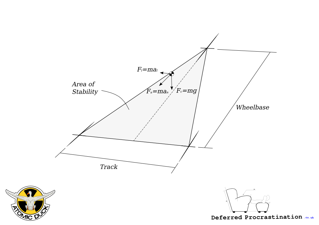
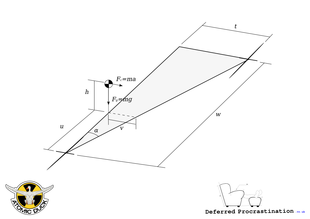 Half-width trike stability diagram
 Free body digram for CofG
[mathjax]
The width of half the stability area at the position of the centre of gravity (v) is:
[ \begin{align} v & = u \tan{\alpha} \
\alpha & = \tan{^{-1} \left( \frac{t}{w} \right) } \
\mathrm{so:} \qquad & \
v & = \frac{ut}{w} \end{align} ]
The resultant force on the CofG ((F_R)) is the vector addition of the two orthogonal forces and the projected length of it at the ground ((l)) are:
[ \begin{align} F_R & = \sqrt{ F_{g}^{2} + F_{c}^{2} } \
\theta & = \tan{^{-1} \left( \frac{F_c}{F_g} \right) } \
& = \tan{^{-1} \left( \left( \frac{mg}{mg} \right) \times a \right) } \\
l & = h \tan{ \left( \theta \right) } \
& = h \tan{ \left( \tan{^{-1} \left( a \right) } \right) } \
\mathrm{so:} \qquad & \
l & = h a \end{align} ]
For the limit conditions,
-
when (l \lt v): the vehicle is stable,
-
when (l = v): roll-over point,
-
when (l \gt v): vehicle has rolled over.
So to calculate the lateral acceleration limit (in multiples of (g)):
[ \begin{align} l & = v \
h · a_{\text{max}} & = \frac{ut}{w} \
a_{\text{max}} & = \frac{ut}{wh} \end{align} ]
This means, with track of 1.56m (t=0.78) that the maximum lateral acceleration occurs at 0.78g (7.651 m/s2).
Weight Distibution
I’ve heard that the weight distribution for a trike is best with a third on each tyre, but this represents a situation where maximum deceleration during braking will be slightly less than cornering performance, and reduced load on the rear tyre under heavy braking could allow directional instability, depending on the centre of gravity height.
It is normally better to think about front/rear weight distribution in terms of axles. You don’t get any more grip just by adding extra wheels to an axle in the same way you don’t get extra grip just by adding wider wheels. All things being equal, as the load on each tyre reduces, the amount of grip for each tyre reduces proportionally (It’s a generality, there are effects by changing the number of wheels and size of the contact patches, but friction doesn’t care about contact area).
Front axle load can be calculated from equilibrium of moments about the rear contact patch:
[ F_{front} = \frac{mgu}{w} + \frac{mah}{w} ]
@ static laden:
-
(F_{front} = 40\%mg)
-
(F_{rear} = 60\%mg)
@ 1g braking:
-
(F_{front} = 56\%mg)
-
(F_{rear} = 44\%mg)
40/60 at static laden is not the ideal 50/50, but it’s not far enough away to cause any drastic handling problems; it’s quite normal to see a modern fwd car around 63/37.
Rob P wrote, “Extra wide track also means extra wide body and extra weight....”