Laser-cut Lattice Living Hinges
AKA: Snijlab-style living hinges, Sninges, Laser cut hinges, or my prefered title: Lattice Hinges
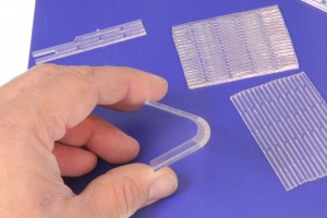 Flexi-Acrylic Test by Solarbotics, on Flickr
After this style of hinge popped up again, this time on Makezine, I was having a look at the linked project guide and at how they worked and I realised that a bit of mathematical modelling could lead to better designed hinges. This could mean fewer rounds of trial-and-error prototype tests, which would reduce the cost of using lattice hinges in a project, and better fatigue resistance, meaning the hinges could be used for moving parts instead of just for static bends.
Download links for the test specimen files are included at the end of this post.
This style of hinge appeared recently in the work of Snijlab, a Dutch laser cutting workshop when they showcased a folding notebook cover mode from a flat sheet of laser cut plywood. They apparently took some inspiration from MEMS hinges; and work by other designers has used some similar principles.
Others soon started to see the usefulness of a hinge that can be cut into flat sheet materials, .:oomlout:. released a plywood arduino box that can be made from only 3 pieces. Solarbotics and @kngunn showed that the lattice cuts also make acrylic, a notoriously brittle material, flexible enough to bend cold.
How do they work?
In addition to giving a hinge, a set of lattice cuts also allow for in-plane expansion and compression prependicular to the line of the cuts.
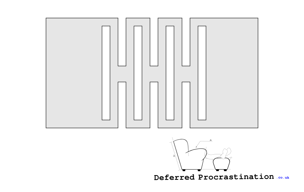 Basic Lattice Hinge Shape
 Lattice Hinge in Compression
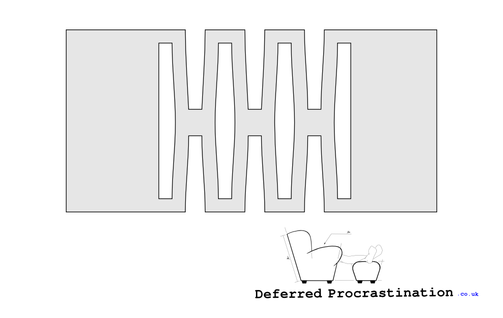 Lattice Hinge in Tension
In tension and compression, there are three repeated parts that allow the distortion to take place: two “Junctions” that do not deform connected by a thin piece that deflects along its length that I’ve dubbed the “Spring Connection”. It’s the elasticity (springiness) of the connection that allows the two ends to move relative to each other, and its this action gives a clue to how the connected system might work as a hinge.
Multiple Torsional Hinges
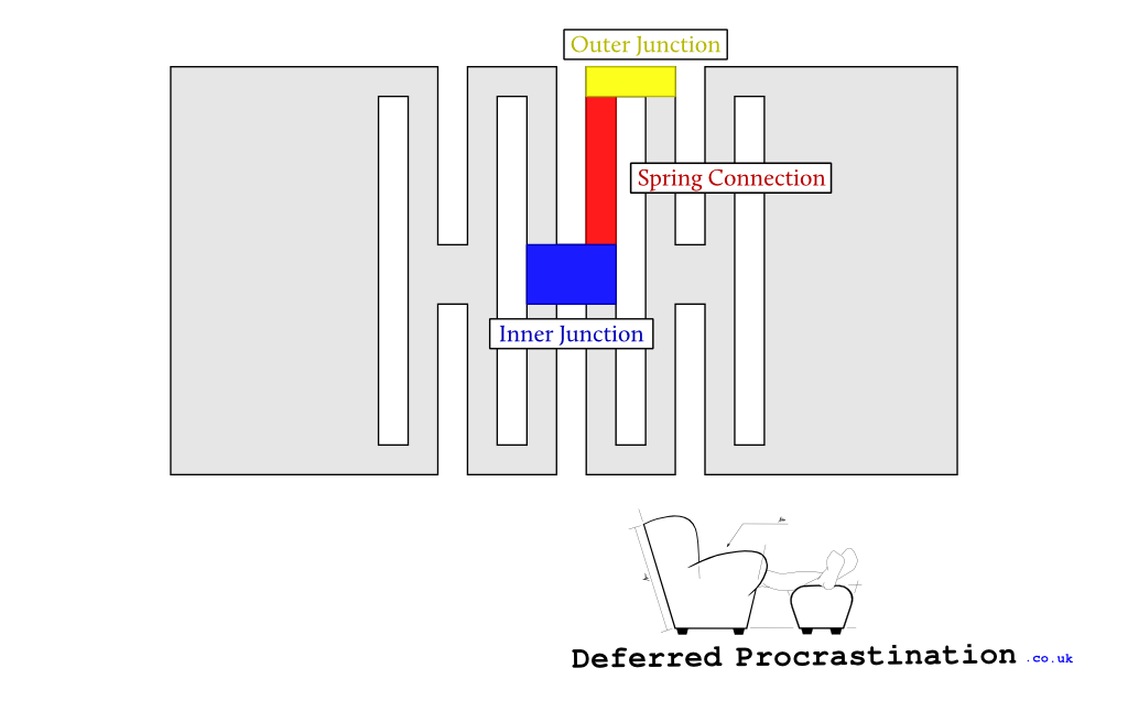 Junctions and Spring Connection
 A Single Spring Connection
 Two Parallel Spring Connections
Assuming that the junctions don’t deflect (or that the deflection is very small) it must be the spring connections that deform by twisting to allow the whole plate to bend. This is similar to how a chain, which has solid links, bends by rotating around the pivots that join each link.
This torsional behaviour is shown clearly in the hinge in use where the outside surface resembles a lattice hinge in tension, and the inside resembles the compression image, but the spring connections also show the twist because each junction end is rotated by a different angle.
 Lattice Hinge in Bending
 Detail of Snijlab’s Hinge in Use
So if each link is loaded in torsion, then it is possible to calculate the material stress of each spring connection. And if the torsion of each connection can be calculated then, in reverse, it is possible to design a connection size that limits the torsional stress in the material, to ensure that the material doesn’t fracture in normal use.
Stress Limitation
If the stress in each spring connection is kept below a the torsional yield stress of the material, then the material will always be operating elastically. This means that the deformation will not be permanent; so once any force is removed, the hinge will return to its original, flat shape (Assuming no plastic creep for polymers). This also gives much better fatigue properties than if the yield stress is exceeded, meaning that the joint could be bent and unbent many times without risk of material fracture — particularly important for acrylic.
Calculating Torsional Stress
Warning: here be formulas. Just skip to the end if you want the results!
If it is true that the spring connection operates in torsion only, then it is relatively straight forward to calculate the maximum torsional stress of that region.
Equations for the calculation of torsional stress can be found at roymech.co.uk
Nomeclature
[mathjax] (T) = Torque (Nm) (l) = Connected length (m) (G) = Torsional Modulus of the material (Pa) (J’) = Polar Moment of Inertia for non-circular sections (m4) (\tau) = Torsional Stress (Pa) (t) = material thickness (m) (n) = number of links in series (\theta) = angle of twist (radians) (\Theta) = total bend angle of the piece ((\Theta = \theta \times n))
Calculation
The total torque of one spring connection is given by: [ T = \frac{\theta{}GJ’}{l} ]
and for a square cross section in the spring link: [ J’ = 0.140625 \times t^4 ]
For one spring connection, the angle of twist is a proportion of the overall bend angle: [ \theta = \frac{\Theta}{n} ]
and the maximum torsional stress in a square member can be given by:
\begin{align}
\tau_{max} & = \frac{4.808 \times T}{t^3}
& = \frac{4.808 \times 0.140623 \times \theta G t^4}{t^3 l}
& = 0.676125 \times \frac{\Theta G t}{n l}
\end{align}
Instead of just calculating stress though, it’s also possible to use the stress limit as a known, and calculate the length and number of spring connections required to stay below the limit stress. I’ve chosen yield stress as the maximum allowed stress, as this is the limit of proportionality of the material, and the limit of non-permanent deformation.
Minimum connections and length
The minimum number of connection links can be calculated by rearranging the previous equation: [ n_{min} = 0.676125 \times \frac{\Theta G t}{\tau_{yield} l} ]
For Acrylic:
(t) = 0.003 m (3mm) (G) = (2 \times 10^9) Pa (2GPa) (\tau_{yield}) = (60 \times 10^6) Pa (60MPa) (\Theta) = (\pi{}/2) rad (90deg)
_I’ve used typical material data from MatWeb (Acrylic, General Purpose, Molded). _
This looks lovely as a graph, but in short:
-
For (l =) 5mm; (n_{min} = ) 21.2 (22)
-
For (l =) 10mm; (n_{min} = ) 10.6 (11)
-
For (l =) 20mm; (n_{min} = ) 5.3 (6)
-
For (l =) 30mm; (n_{min} = ) 3.5 (4)

Practical Testing
Of course, this is all mere speculation without any actual testing(!). As I don’t have direct access to a laser cutter, I’ve sent for a set of test pieces to be cut, and I’ve also received a set of courtesy of .:oomlout:. in both 3mm acrylic and 3mm MDF. While I haven’t had time to test these fully, the acrylic is still brittle; I’ve already broken one hinge (oops!) and only the smallest ((l =) 5mm; (n = ) 22) specimen is able to bend to 90 degrees.
This seems to suggest then that the my calculation is not quite accurate, though a few possibilities why come to mind:
-
The material data I’m using is not quite the same as the acrylic for cutting.
-
The material properties are affected by the heat of cutting.
-
The stress is greater in practice because I’ve ignore the kerf of the laser.
-
Choosing torsional yield stress as the limit stress is too high for dynamic bending (hence why I’ve shown 60% torsional yield stress in the graph too).
So there’s still a bit more work to do, however in the mean time , here in the zip file with the cutting diagram for these specimens if you’d like to try it your self: DOWNLOAD

Comments, questions, corrections and suggestions are welcomed.
LINDA MIRANDA wrote, “Hola amigo, consulta me puedes vender los planos en formato Ilustrador o en DWJ o en DXF y cual es el costo, gracias”