Steering for the finish
I seem to have spent quite a long time looking at bearings this week, to generate an attachment method for the steering wheel and column that is simple to manufacture. The complexity of the choice comes from the combined loading where the steering column is held (axial, radial and moment loads) and having a flat mounting plate. However, if you’re just here for the pretty CAD pictures, I don’t need to keep you any longer:
 Steering Layout - Rider View
 Steering Layout - Pulley Side
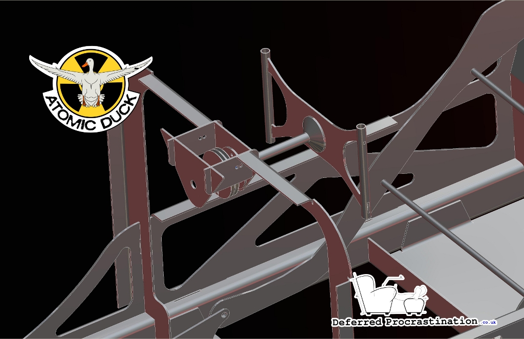
You can see the steering wheel, with the standard, bike-sized bars for each grip. The extra length at the top and bottom gives a number of mounting locations for brake levers and any shifters. On back side of the assembly, the pulley accepts two cables (one for pull left, and one for pull right), one in each side, which wrap around the pulley and convert the wheel rotation into the pulling motion for the cable steer. The steering ratio is around 1:5, so full lock is just over 180° rotation of the wheel.
All that’s missing from the model at the minute is the M12 bolt that secures the wheel centre to the steering column (the connecting face uses epoxy bonding to prevent the wheel rotating without the shaft) and the M12 locknut that secures the pulley in place and clamps up the bearings.
While most of the parts in Atomic Duck are cut aluminium (sheet, plate and stock), The steering column is the first piece that needs to be cut on a lathe. I’ve tried to keep it to as few pieces as possible, but I have had to use an unusual method of joining the pulley to the column to avoid any splines.
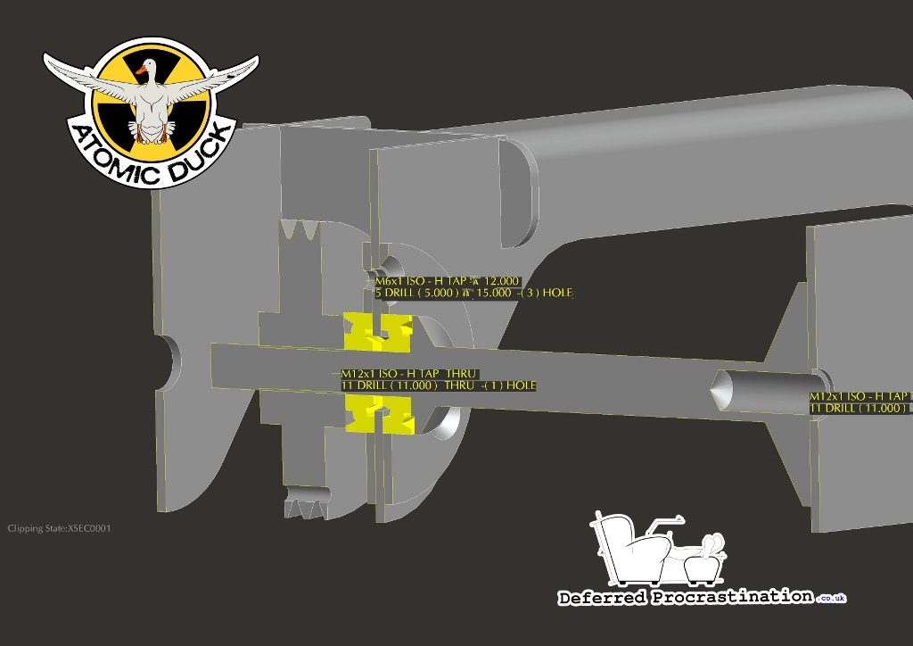 Steering Cross Section
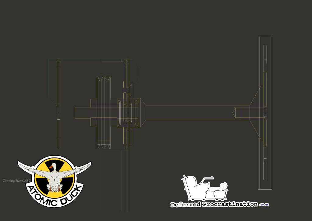 Steering Cross Section (2D)
Behind the bearing pair, the steering column shaft is threaded to match the hole through the centre of the pulley, and the pulley is used to clamp the bearing pair to the dash plate. Behind the pulley, a locknut is used to hold the pulley in place on the shaft, and stop it from unscrewing. If the pulley and locknut are locked together fully, this should mean that any rotational force should transfer between the steering column shaft and pulley, because the pulley can’t move along the shaft. This is similar in principal to when you lock two nuts together to screw/unscrew a threaded stud.
For the bearing pair, I’ve specified a pair of angular contact ball bearings, mounted back to back across the dash plate. The angular contact bearing can transmit both axial and radial forces, and when used as a pair is very good at resisting bending moments on the shaft. However, to carry the radial forces, the bearing needs to be located radially, usually by fitting into a circular groove that is machined into the contact face. Because I don’t want to include extra machining steps into the creation of the dash plate (I’ve already included some additional bends to increase the stiffness, to better carry the loads through the steering wheel) I’ve added two annuli, secured by three M6 bolts; one to each face of the dash plate. The reverse side annulus has threaded holes.
Bonus points this week if you spotted the change in the bottom bracket adjustment in the background of the first image. The nine-hole bolt-through adjustment is now just a slot, so the pedal length can be more finely adjusted. The bolt position has also been moved further from the bottom bracket location, to remove any clearance problems.
James Murphy wrote, “An idle thought, might it be worth considering adding a second bolt for the bottom bracket adjustment? Under some circumstances (starting, in the wrong gear, well laden) there will be a lot of force applied.”