Bottom Bracket and Adjustment
The bottom bracket structure was not quite ready to show last week (although I put up pictures) but it’s much better this week. If you don’t feel there’s been much obvious progression from those images, you’re not alone, I keep putting in the hours on the CAD, and it doesn’t seem to change shape much!
This is exactly what should be expected though, the blocking out of the structure is like a first draft of a piece of writing. Once you have a good basis to work from, it’s all a lot if tweaking, adjusting, calculating, redrawing and moving around to finish it.
What you’re looking at is still without the cross-supports for the long members (to make then into I-beams), a rider facing chain cover and the tabs and slots to allow it all to self jig.
Chainline and Chain Guard
The images below show the dash bulkhead at the rear, but not the forward bulkhead that the front of the bottom bracket assembly attaches to, to make it all easier to see. It’s not all hanging out in space really!
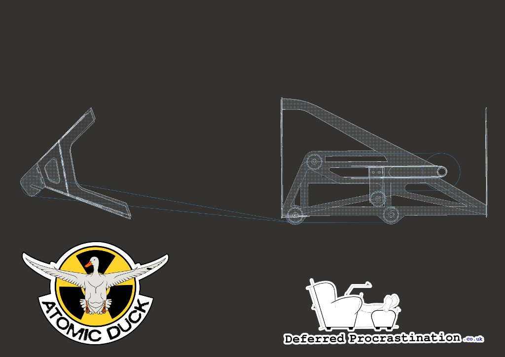
Where last week’s images didn’t show the rearward chainguard, it is included here. I’d actually like to extend the guard forward towards the pedal chainring, but I haven’t got a good enough model of a pedal assembly to ensure the guard would lie between the pedal crank and the sprocket, and I’ve no idea how the clearance changes with single, double and triple front chainrings — so that’s on the “to-do” pile.
The chainguard currently covers the top-idler, the lower-front and lower-rear pair of idlers and the run of the idler attached to the arm from the bottom bracket slider (the sliding idler).
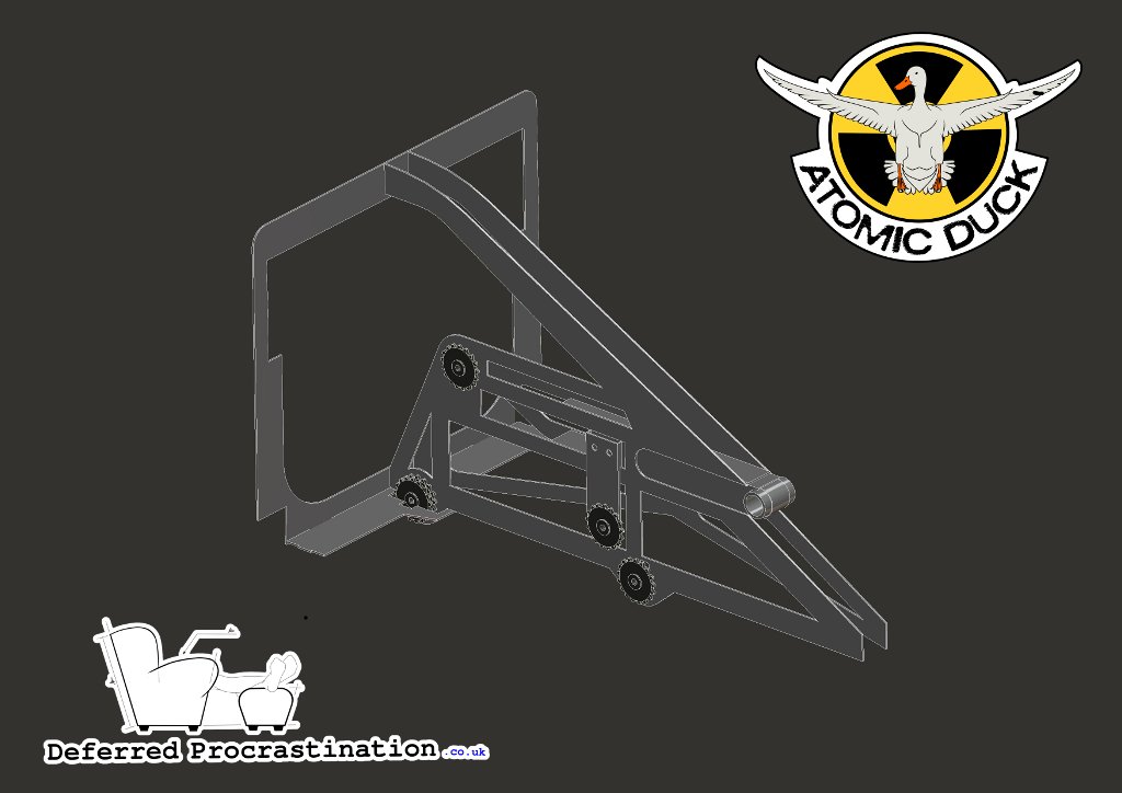 A004_R002 Chainline Assembly
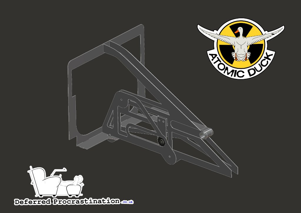 A004_R002 Right View with Chain Cover
The assembly structure rises up to meet the dash bulkhead to give structural support to the area where the steering wheel will be mounted and to provide the brackets that will mount the steering cables. Expect this area to evolve as the steering assembly is re-engineered.
Adjustment
A single vertical bolt secures the bottom bracket slider (shown outlined in red), which is plated in on four sides. The bottom bracket shell is connected to the bottom bracket slider with a 1mm aluminium band that is bonded to the inside of the slider, keeping the outside profile of the slider constant.
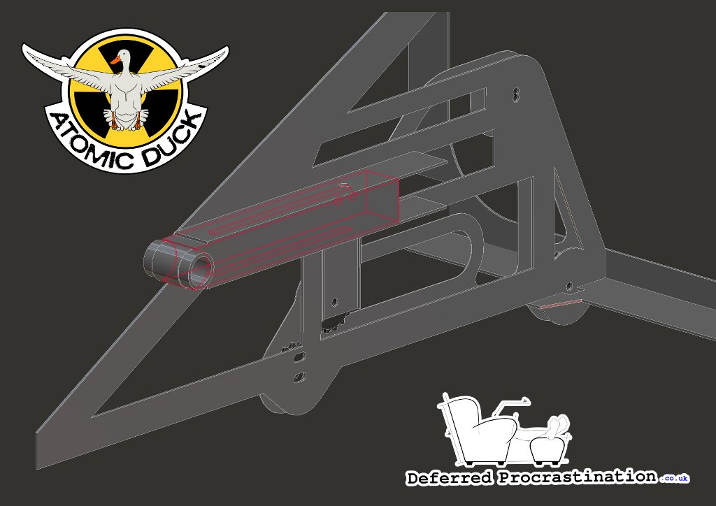 Sliding Bottom Bracket Adjustment
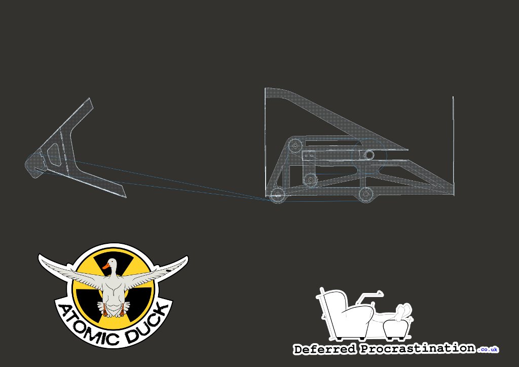
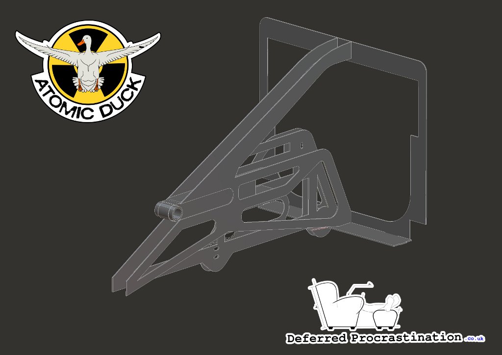 A004_R002 Left View
The middle idler moves with backwards and forwards with the bottom bracket, so any reduction in the distance between the top idler sprocket and the chainring is equal to the increase in distance between the lower-forward idler and the sliding idler. Adjustment for chain tension (when the chain run is not an exact multiple of chain link length) is in a slide mount for the lower-front idler.
Horizontal adjustment of the bottom bracket is 220mm (0.22m), which is designed to allow rider leg lengths from a 5th percentile female up to a 95th percentile male (rider height 5’1” to 6’3” with seat rake adjustment).
 A004_R002 Fully Forwards
 A004_R002 Fully Back
Images show for a 52T chainring and 17T idler sprockets. I’ve got some holes to match for a 39T chainring, but the mounting points will have to be necessarily limited.