Solidly Mounted Steering
well, not solid, it’s no good if you can’t turn the wheel!
Before I show the complete steering assembly, I wanted to show the detail of the steering pulley, where the driver’s end of the steering cables connects to the steering wheel and how all the parts clamp up around the dash panel to allow the wheel assembly to rotate.
 Steering Pulley Assembly
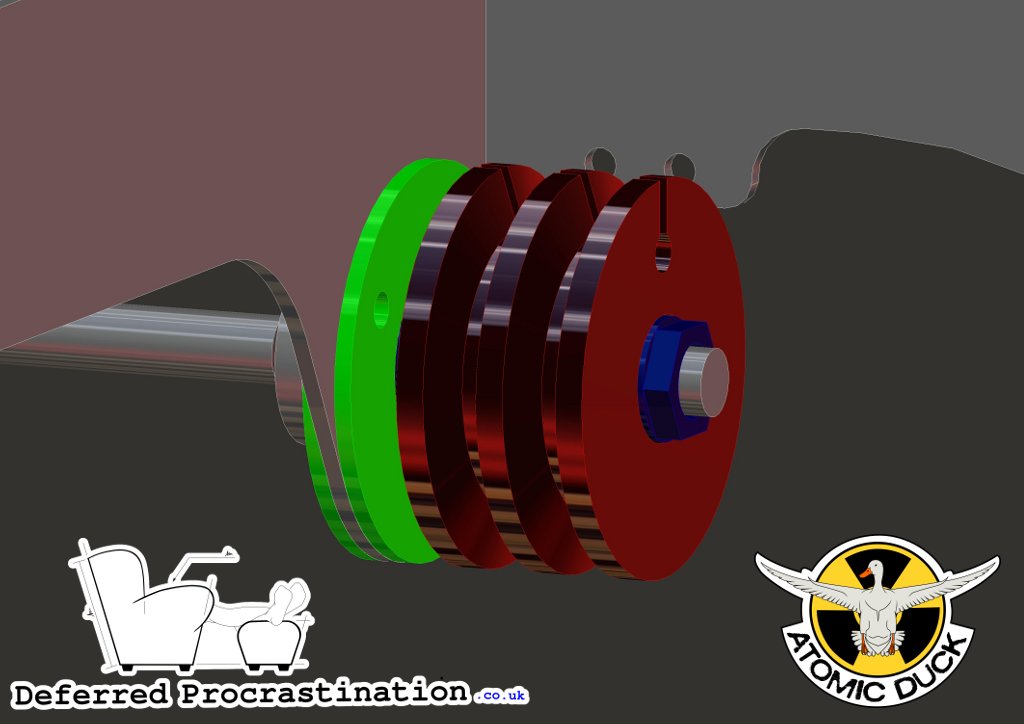 False Colour Assembly
Here you can see the whole assembly, the Steering Pulley (A005_P006_R002) is in red, slotted at the top to accept the ferrule at the end of the cable. Then the cable loops the pulley once and passes though one of the holes in the background, where the side plates of the pedal assembly meet the dash panel (One cable through the panel in the background, and one looped the opposite way round the pulley and passing through one of the hole son the opposing plate — not shown for clarity). The holes also hold the termination of the cable sleeve, allowing some minor adjustment of cable tension at this point, though the major adjustment is at the wheel-end of the cable.
While the pulley geometry I’ve chosen is very similar to available V-Belt pulleys (an SPZ 63mm pulley would have similar external dimensions) I’m not using an off-the-shelf pulley for 2 reasons:
1, The traditional way of attaching a pulley to a shaft is to cut a keyway into the shaft and use a taper bore bush to clamp the pulley around the shaft, but this means that it’s not possible adjust the position of the pulley around the shaft, it has to be set at one point. Using a non-keyway centre fastening means that the angle of the pulley can changed compared to the wheel, and this mans that the wheel can always be set level at straight ahead steering. However, using a non-keyway fastening means it’s not possible to use the widely available tapered bush pulleys, so any standard pulley would still need machining to fit the shaft.
- Using a non-standard pulley means I can fine-tune the exact diameter that the cable runs round, meaning that I can better control the steering ratio. As I said before, an SPZ 63mm OD pulley has similar dimentions, but they would not give exactly the same steering effect.
 Steering Pulley Cutaway
In the cross-sectional diagram, you can see better how the machined pulley centre actually clamps up the bearings of the steering boss. The keyless fastener (Transtorque shown in blue) applies a radial clamping force to both the pulley and the shaft, and also provides some axial resistance too. This means that it can also be used as the single fitting that controls the bearing preload, as well as the axial position of the pulley around the shaft.
The shaft bearings (shown in yellow, a pair of 1201 self aligning ball bearings) are clamped between the flange of the steering shaft, and the pulley. Using M12 washers between the components means that they can both be flat sided — simplifying manufacturing — and still only contact the inner race of the bearings.
To locate the outer races of the bearings, two retaining plates (shown in green — A005_P004_R002) are bolted through the dash panel to surround the bearings and control their location radially. The hole in the dash panel is noticeably larger than the diameter of the steering shaft so it only contacts with the outer race of the bearings.