So What's a Practical Laser-Cut Clip Size?
I’ve previously shown for laser-cut elastic-clips for comb joints what the equations are for calculating maximum bending stress and operating force, using the distance that the clip has to deflect in use as the starting point. I also explained how a tapering clip profile was preferable to a straight one. This time I’m going to share an example of a practical clip geometry that I’ve been using regularly to hold small parts together in 3mm acrylic.
While the clip is useful as a component of other parts, it’s helpful to see how it is used to make something practical, so I’ve also made a clip-together box that can be completely made from laser cut acrylic, with no other parts or tools needed. Both the clip geometry and the box are available on thingiverse for you to download, use and remix.
As a measure of how robust the clips that hold the box together are, we’re now also producing some Raspberry Pi cases using a derivative of the box design above. Manufactured in Liverpool, in the UK, we have some of the first batch available to buy in the shop now. (More on the Clip-R-Pi cases next time)
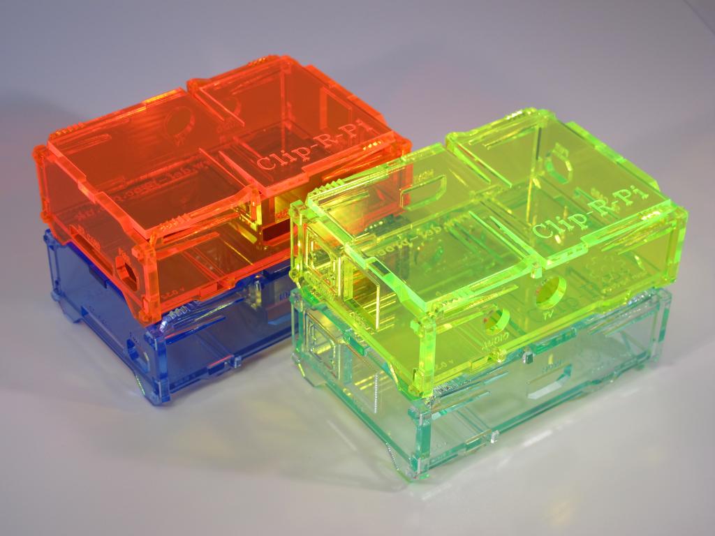 Clip-R-Pi, laser-cut clipped-together Raspberry Pi cases
The clip geometry that I’ve got is nothing more than putting the values of \(a\), \(b\), \(d\) and \(l\) into a spreadsheet and adjusting them to come up with a geometry for reasonable values for operating force, \(F\), and maximum stress, \( sigma_{max}\).
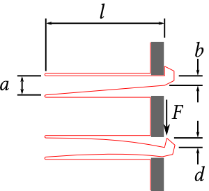 Tapered Clip Dimensions
From last week, operating force is given by: \[ F = frac{dEt(a-b)^3}{4l^3} \]
And the maximum stress at the root is given by: \[ sigma_{max} = frac{6Fl}{ta^2} \]
Where \(E\) is the Young’s modulus of the material and \(t\) is the sheet thickness. Note that material thickness does not change the maximum stress in the clip (as stress is force per unit area) so using thicker sheet will only increase the force required to operate the clip.
Also relevant for sizing is the pull through force (\(P\)): the force at which trying to pull the clip out of the slot causes the bending moment at the clip head becomes great enough that it will overcome the stiffness of the clip and unclip itself. This is a ratio of the clip length and the head size (which will equal \(d\)): \[ P = frac{Fl}{d} \]
For this clip geometry,
-
\(a = 4\)mm
-
\(b = 2\)mm
-
\(d = 2\)mm
-
\(l = 25\)mm
Which gives
-
\(F = 2.46\)N, which is possible with a fingertip pinch.
-
\( sigma_{max} = 7.68 \)MPa which is comfortably below the \(60\)MPa Yield stress limit for acrylic.
-
\(P = 30.72\)N
Robustness
While the clip above is shown to stay well below the maximum stress of the material, some manufactured clips that use that exact geometry may break when used. The problem is the end of the cut on the flat (top) side of the clip ends right at the position of maximum stress, which will be in tension when the clip is operated, and acts as a stress riser, making the acrylic more likely to break at that point.
The simplest way to counter this is to move the end of the cut away from the position of maximum stress by extending the cut further. Adding an additional 5mm to the length of the cut is sufficient to remove the risk of failure in the clip.
 Adding 5mm to the cut moves the stress riser position
Other Materials
While this clip is sized for acrylic it also works very well in MDF, although the clip head will break off well before the pull through force. However, this style of clip doesn’t work for plywood because the clip head tears off very easily; because of the weakness of having multiple unidirectional fibres in layers being twisted over a very small area, the clip head easily shears between layers, and along the fibre direction.
A Raspberry Pi case using this clip method for construction is available to buy now in the shop and examples are available to download for use in your own designs from thingiverse.
Todd Mory wrote, “Nice analysis! I've tried clips like this, to make an Android tablet stand. I made "l" much shorter, and it broke the clips. I'll retry it with your dims. Good idea to stagger the cuts, and relieve some of the stress concentration! We're going to use this method to design and test box prototypes for Techmor systems. www.techmor.com Thanks for sharing.”